See the Heat
Heat, exactly, is measured by calorimeter. Since content of this article exploits temperature which is measured by
thermometer, its headline is incorrect, in deed. Inexorably it should be “See the Temperature”. While usually people care about heat
when they refer to temperature, it goes onwards along with this everyday sense. It also would loose its attractive rhyming resembling phrase Feel the heat!
.
HW used:
Further reading guides through implementation and notes on transforming temperature degrees into RGB LED light.
Note: Any upcoming information regarding pulse width modulation used to drive color mixing are just terse, not dissected in details. However related code parts are lucid on their own.
Get Started 🌐
Since temperature is relatively stable quantity, no measuring of it eventuates at all. On how to do exactly this with MCU die thermometer see reference at article end. Instead simulation is used so “every” temperature can be measured.
“Every” is quoted since real die thermometer has its resolution (0.25 °C step), range (-40 – 105 °C) and accuracy (±5 °C). See also https://tech.microbit.org/hardware/#temperature-sensing.
struct ThermometerImitation {
    val: f32,
    min: f32,
    max: f32,
    ste: f32,
}

impl ThermometerImitation {
    fn read(&mut self) -> f32 {
        let val = self.val;

        self.val = if val >= self.max {
            self.min
        } else {
            val + self.ste
        };

        self.tim.delay_ms(self.del);
        val
    }
}
That is thermometer simulator. It is initialized with: range defined as minimum and maximum, step and current value. Reading value means cycling over increments from minimum to maximum.
const MIN_CEL_DEGS: f32 = -50.0;
const MAX_CEL_DEGS: f32 = 60.0;
const PRESCALER: Prescaler = Prescaler::Div8;
const PERIOD: u32= 7800;

const RGB_POIS: f32 = 256.0;
const CEL_DEGS: f32 = 110.0;
const POI_PER_DEG: f32 = RGB_POIS / CEL_DEGS;
const DOU_POI_PER_DEG: f32 = POI_PER_DEG * 2.0;
Constants come about more interesting.
MIN_CEL_DEGSandMAX_CEL_DEGSrepresent inclusive temperature range.PRESCALERof valueDiv8means 2 Mhz.- In combination with
PERIODby formula 2 Mhz ÷ 7 800 Hz it produces maximal duty cycle value for PWM. RGB_POIS— RGB degrees compose of integer values 0-255 both side inclusively = 256.CEL_DEGS— 50 negative + 60 positive degrees make up 110 degrees.POI_PER_DEG— simple ratio numbering RGB points per one Celsius degree.DOU_POI_PER_DEG— double ratio.
Interestingly, 2 000 000 ÷ 7 800 = 2 k ÷ 7.8 ≅ 256.41 ⟹ 256 maximum duty cycle. That noticible means that duty cycle supports values from 0 to 256 where 256 means off.
Blending Strategy 🌐
Blending requirements:
- Freezing temperatures go with cold color, ist est white.
- Cool and mild are expressed with green and yellow.
- Warm and hot by red.
#![no_main]
#![no_std]
use panic_halt as _;
use cortex_m_rt::entry;
use microbit::pac::PWM0;
use microbit::Peripherals;
use microbit::hal::{
gpio::{p0::Parts, Level},
prelude::_embedded_hal_blocking_delay_DelayMs,
pwm::{
Channel::{C0 as CHRED, C1 as CHGREEN, C2 as CHBLUE},
CounterMode, Prescaler, Pwm,
},
time::U32Ext,
Timer,
};
#[entry]
fn main() -> ! {
let p = Peripherals::take().unwrap();
let mut tim = Timer::new(p.TIMER0);
let mut meter = ThermometerImitation {
val: MIN_CEL_DEGS,
min: MIN_CEL_DEGS,
max: MAX_CEL_DEGS,
ste: 0.1,
};
let pwm0 = Pwm::new(p.PWM0);
let p0 = Parts::new(p.P0);
pwm0.set_counter_mode(CounterMode::Up)
.set_prescaler(PRESCALER)
.set_period(PERIOD.hz());
set_max_duty_on_all(&pwm0);
pwm0.set_output_pin(CHRED, p0.p0_02.into_push_pull_output(Level::Low).degrade())
.set_output_pin(
CHGREEN,
p0.p0_03.into_push_pull_output(Level::Low).degrade(),
)
.set_output_pin(CHBLUE, p0.p0_04.into_push_pull_output(Level::Low).degrade());
let max_duty = pwm0.max_duty() as f32;
loop {
let val = meter.read();
if val < MIN_CEL_DEGS || val > MAX_CEL_DEGS {
set_max_duty_on_all(&pwm0);
continue;
}
let blue_amount = if val < 5.0 {
(val - MIN_CEL_DEGS) * DOU_POI_PER_DEG
} else {
max_duty
};
let green_amount = {
let magic_corrector = 0.6 - if val > 30.0 { (val - 30.0) * 0.02 } else { 0.0 };
(val - MIN_CEL_DEGS) * (POI_PER_DEG + magic_corrector)
};
let red_amount = POI_PER_DEG * {
if val < 5.0 {
val - MIN_CEL_DEGS
} else {
MAX_CEL_DEGS - val
}
};
pwm0.set_duty_on(CHRED, red_amount as u16);
pwm0.set_duty_on(CHBLUE, blue_amount as u16);
pwm0.set_duty_on(CHGREEN, green_amount as u16);
tim.delay_ms(5u32);
}
}
// cargo flash --target thumbv7em-none-eabihf --chip nRF52833_xxAA --release
fn set_max_duty_on_all(pwm0: &Pwm<PWM0>) {
let max_duty = pwm0.max_duty();
for ch in [CHRED, CHGREEN, CHBLUE] {
if pwm0.duty_on(ch) != 0 {
pwm0.set_duty_on(ch, max_duty);
}
}
}Initialization is straight:
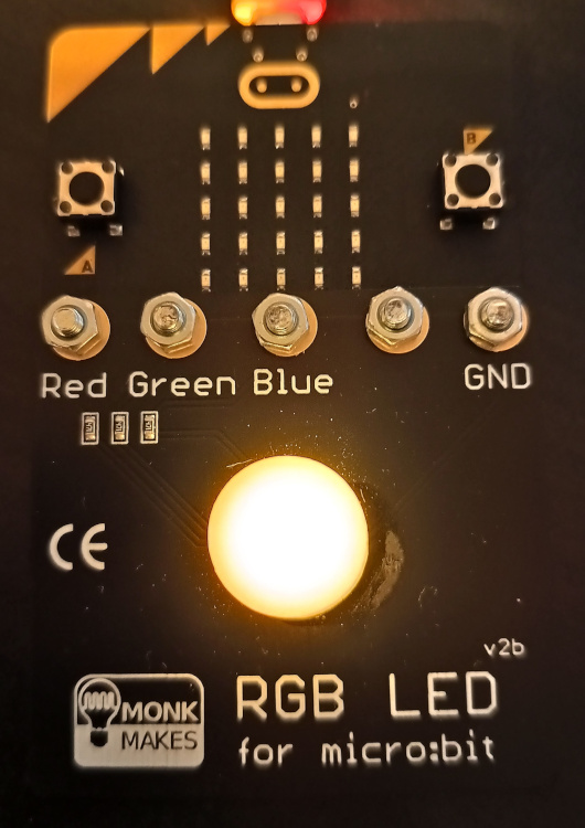
- PWM0 is initialized so it uses 3 of its 4 compare channels to drive RGB inputs on RGB card.
- Timer serves for delaying that makes color transitions noticible.
- Thermometer simulator is provided with known constants and small fractional step for even graduation.
Setting all channels to maximum duty effectively disable them. This prevents sudden flash after 1st measurement. Internal mapping of pins can be read from documentation ([0,1,2] = [R,G,B]). Unsupported measurement value results in no LED emission.
Cold, white ⬜, color is generated by composition of all other colors. To achieve this all colors are high "all the time" at beginning. Blue 🟦 fastly shortens its high-times towards middle of scale. Where it shuts off. Red 🟥 do same as blue but half slowly. Also from scale middle it raises its high-times, again with same tempo. Most interesting is green 🟩 color. This lowers its high-times from scale bottom to scale top. It uses magic_corrector to speed up little its slow tempo. Thus temperatures around 30 °C are red already. When more than 30 °C, then it lowers its decreases to high-times up to top of scale where it shuts off.
Duty cycle values are computed using RGB point ratio and actual temperature measurement value after relevant correction.
[package]
name = "see_the_heat"
authors = [ "software9119.technology" ]
version = "0.0.1-alpha"
edition = "2021"
license = "MIT"
[dependencies]
microbit-v2 = "0.12.0"
cortex-m = "0.7.3"
cortex-m-rt = "0.7.0"
panic-halt = "0.2.0"Outcome 🌐
This all results in color representation of temperatures in scale used.
Green color is not really distinctive but this is only due to recording properties. For almost identic project see see_the_heat.