Advanced LED matrix messaging
This article is based on example. So, no kudos for me at all.
Topics not discussed in deep or at all:
- Interrupts: handlers, priorities, critical sections.
- Thread-safety: atomics, mutexes.
- Language instruments: statics, constants, closures, …
- Clocking: real time counters, timers, frequencies.
- Embedded development with Rust in general.
Note: crate cortex_m_rt documentation provides tight-bound information on implementions used.
Basic Setup 🌐
Let have sneaky peek on setup. Basically this goes with guide provided at Module microbit::display::nonblocking and woking example already mentioned.
In short, control over display is taken, randomization and timing is prepared along with interrupts — short note on priorities: lower is better and displaying gets precedence “in order to not miss something” while RTC0 drives progress.
#![no_std]
#![no_main]
use panic_halt as _;
use core::cell::{Cell, OnceCell, RefCell};
use cortex_m::interrupt::free as interrupt_free;
use cortex_m::interrupt::Mutex;
use cortex_m_rt::entry;
use microbit::hal::Rng;
use microbit::{
display::nonblocking::{Display, GreyscaleImage},
hal::rtc::{Rtc, RtcInterrupt},
pac::{interrupt, RTC0, TIMER2},
};
static DISPLAYOR: Mutex<RefCell<Option<Display<TIMER2>>>> = Mutex::new(RefCell::new(None));
static ANIMATOR: Mutex<OnceCell<Rtc<RTC0>>> = Mutex::new(OnceCell::new());
static RND: Mutex<Cell<Option<Rng>>> = Mutex::new(Cell::new(None));
#[entry]
fn entry() -> ! {
use microbit::board::Board;
use microbit::pac::{Interrupt, NVIC};
let mut board = Board::take().unwrap();
microbit::hal::clocks::Clocks::new(board.CLOCK).start_lfclk();
let mut rtc0 = Rtc::new(board.RTC0, 162).unwrap();
rtc0.enable_interrupt(RtcInterrupt::Tick, None);
rtc0.enable_counter();
let display = Display::new(board.TIMER2, board.display_pins);
let rnd = Rng::new(board.RNG);
interrupt_free(move |cs| {
DISPLAYOR.borrow(cs).replace(Some(display));
_ = ANIMATOR.borrow(cs).set(rtc0);
RND.borrow(cs).set(Some(rnd));
});
unsafe {
board.NVIC.set_priority(Interrupt::RTC0, 64);
board.NVIC.set_priority(Interrupt::TIMER2, 32);
NVIC::unmask(Interrupt::RTC0);
NVIC::unmask(Interrupt::TIMER2);
}
loop {}
}TIMER2 handler 🌐
Following instructions from module documentation we need to make:
In an interrupt handler forthe timer call .handle_display_event()
#[interrupt]
fn TIMER2() {
    interrupt_free(|cs| {
        let borrow = DISPLAYOR.borrow(cs);
        let mut refmut = borrow.borrow_mut();
        refmut.as_mut().unwrap().handle_display_event();
    });
}
Demand is satisfied as should be: in interrupt handler for timer passed to Display instance
handle_display_event() is called on instance in question.
RTC0 handler 🌐
Now main topic of this articles is discussed: something to display. Let start with code sample and then discuss parts of interest.
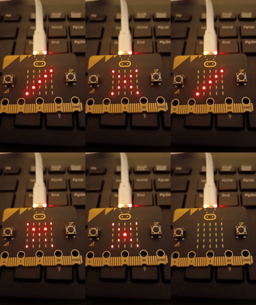
This code drives LED matrix to show righ-left and left-right diagonals and cross that they compose. To make this more visually attractive, Rng randomization and GreyscaleImage brightness capability are leveraged.
#[interrupt]
unsafe fn RTC0() {
    use core::sync::atomic::{AtomicU8, Ordering};

    interrupt_free(|cs| {
        let animator = ANIMATOR.borrow(cs).get().unwrap();
        animator.reset_event(RtcInterrupt::Tick);
    });

    static mut SCALER: AtomicU8 = AtomicU8::new(0);
    static mut PHASE: AtomicU8 = AtomicU8::new(0);

    if SCALER.fetch_add(1, Ordering::Relaxed) < 42 {
        return;
    } else {
        SCALER.swap(0, Ordering::Relaxed);
    }

    const LEF_RIG_DIA: fn(usize) -> Option<usize> = |rix| Some(rix);
    const RIG_LEF_DIA: fn(usize) -> Option<usize> = |rix| Some(((rix as isize - 4) * -1) as usize);

    let phase = PHASE.load(Ordering::Relaxed);
    let lighter = match phase {
        0 | 5 | 7 | 9 => |rix| [LEF_RIG_DIA(rix), None],
        2 | 4 | 8 | 10 => |rix| [RIG_LEF_DIA(rix), None],
        1 | 3 | 6 | 12..=21 => |rix| [LEF_RIG_DIA(rix), RIG_LEF_DIA(rix)],
        11 | 22 => |_| [None, None],
        _ => panic!("All phases have to be handled by some arm."),
    };

    PHASE.store((phase + 1) % 23, Ordering::Relaxed);

    let mut disp_latt: [[u8; 5]; 5] = [
        [0, 0, 0, 0, 0],
        [0, 0, 0, 0, 0],
        [0, 0, 0, 0, 0],
        [0, 0, 0, 0, 0],
        [0, 0, 0, 0, 0],
    ];

    let mut rnd = interrupt_free(|cs| {
        let borrow = RND.borrow(cs);
        borrow.take().unwrap()
    });

    for rix in 0..5 {
        let brightness = match phase {
            1 | 3 | 6  => 7,
            12..=21 => {
                let rnd = rnd.random_u8() % 10;

                match rnd {
                    0..=5 => 5,
                    x => x,
                }
            }
            _ => 8,
        };

        for cix in lighter(rix) {
            if cix.is_none() {
                break;
            }

            disp_latt[rix][cix.unwrap()] = brightness;
        }
    }

    let gsi = GreyscaleImage::new(&disp_latt);

    interrupt_free(|cs| {
        let rnd_borrow = RND.borrow(cs);
        rnd_borrow.set(Some(rnd));

        let dis_borrow = DISPLAYOR.borrow(cs);
        let mut refmut = dis_borrow.borrow_mut();
        refmut.as_mut().unwrap().show(&gsi);
    });
}
// cargo flash --target thumbv7em-none-eabihf --chip nRF52833_xxAA  --release
[package]
name = "advanced_led_matrix_messaging"
version = "0.0.1-alpha"
edition = "2021"
authors = ["software9119.technology" ]
license = "MIT"
[dependencies]
microbit-v2 = "0.13.0"
cortex-m = "0.7.7"
cortex-m-rt = "0.7.3"
panic-halt = "0.2.0"
1st interesting part is block starting with line if SCALER.fetch_add(1, Ordering::Relaxed) < 42 {. Why it is interesting? Because of Rtc::new(board.RTC0, 162). new documentation informs that fRTC = 32_768 / (prescaler + 1 ). Having 162 that means circa 200 Hz resulting frequency.
Having 200 Hz frequency means tick every 5 ms. Handy SCALER here makes timing more feasible because
one can simple choose some base value, 5 ms in this case, and scale it quickly by multiplying without need to recompute prescaler. If it is even possible. Documentation suggests it indirectly, nonetheless maximum prescaler is 4095. Thus frequency ranges from 8 Hz to 32.768 kHz.
Once tuning is finished, prescaler value can be, of course, recomputed so cycles are not generated in vain. For circa 215 ms of this configuration, this is impossible since slowest cycle available is 125 ms.
2nd interesting part regards visual attractivity. For phases where sole diagonal is displayed, constatnt brightness 8 is chosen. On other hand for cross consecutive phases, each row goes with randomized and normalized brightness level. Normalization is apt since lower brightnesses are quite dim. Cross brightness varies from 5 to 9 and also goes with constant 7.
3rd interesting part is phasing of diagonals and crosses. Let say some vivid scheme was designed that also uses 2 blank phases.
Conclusion 🌐

- Interesting parts of implementation were discussed. That showed some options how to manage advanced displaying with microbit:v2.
- As of writing this article there is small bug in displaying with unreleased fix.
- For similar example of advanced displaying see mcu_chats_with_you_2.